)
Inhaltsverzeichnis
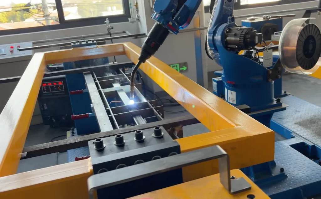
Geschweißte Rahmen tragen Maschinen, Förderer, Karren, und Vorrichtungen. Das richtige Toleranzschema macht den Unterschied zwischen einer reibungslosen Installation und kostspieligen Nacharbeiten aus. Als in China ansässiger OEM/ODM Fabrik, Able Hardware baut Präzisionsrahmen mit Automatische/Robotermig (und WIG, sofern angegeben), integrierte CNC-Bearbeitung, und exportfähige Qualitätsdokumentation. Diese Anleitung zeigt, wie man GD anwendet&T zu geschweißten Rahmen, sodass Sie sie einmal kaufen und schnell installieren können.
Wo GD&T schafft Mehrwert
- Kommuniziert Funktion (fit, bilden, und Orientierung) anstatt „überall eng“ zu raten.
- Verhindert Übertoleranzen, die die Schweißzeit verlängern, Befestigung, Bearbeitung, und Beschichtungsnacharbeiten.
- Ermöglicht eine skalierbare, auf das Risiko abgestimmte Inspektion – von Schweißnahtmessgeräten bis hin zu KMG/Laserscannern.
Für Produktionsbeispiele, siehe unsere Kundenspezifische Metallrahmen und Schweißwagen.
Datumsstrategie für Frames
Wählen Sie „Stabil“., Funktionale Bezugspunkte
- Primär (EIN): Die Montageebene oder die Basispolster, die mit dem Boden verbunden sind, Maschinenbett, oder rutschen. Definieren Sie A als breit, stabile Ebene nach jeder Bearbeitung nach dem Schweißen.
- Sekundär (B): Eine lange Referenzschiene oder bearbeitete Kante, die die Teileausrichtung entlang der Länge steuert.
- Tertiär (C): Ein Querträger oder ein bearbeitetes Loch/ein Schlitz, der die Drehung sperrt.
Tipp: Wenn der Rahmen pulverbeschichtet ist, Bezüge definieren auf unbeschichtet Bearbeitete Pads, um ein Stapeln aufgrund der Beschichtungsdicke zu vermeiden.
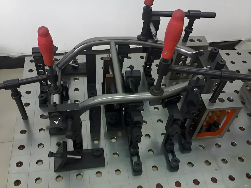
Reihenfolge und Fixierung
Aufbieten, ausrufen, zurufen "Termine nach dem Schweißen, vor dem Beschichten” wenn die Pads nach dem Schweißen punktförmig sind. Wir verwenden spezielle Vorrichtungen und Roboterperlen, um den Wärmeeintrag zu stabilisieren.
Gd&T-Steuerungen, die am besten bei geschweißten Rahmen funktionieren
Geradlinigkeit & Ebenheit
- Geradlinigkeit von Rohrschienen: 0.5–1,0 mm pro Meter typisch für Bauteile im Schweißzustand.
- Ebenheit der Basisebene (EIN): 0.3–0,8 mm pro 300 mm wie geschweißt; 0.1–0,3 mm nach der Bearbeitung.
Parallelität & Rechtwinkligkeit (Rechtwinkligkeit)
- Parallelität zwischen Oberdeck und Basis A: 0.3–0,6 mm pro 300 mm wie geschweißt; 0.1–0,2 mm bearbeitet.
- Rechtwinkligkeit der Pfosten zu A: 0.2–0,5 mm pro 100 mm.
Position für Lochgruppen
Verwenden wahre Position mit MMC für Schraubenmuster an Polstern und Halterungen:
- Ø0,3–0,6 mm (bearbeitet) oder Ø0,8–1,5 mm (geschweißte Lochbleche) ihr Datum A|B|C.
- Für lange Schienen, anwenden zusammengesetzte Position um die Wiederholbarkeit von Muster zu Muster aufrechtzuerhalten und gleichzeitig ein Schienenwachstum zu ermöglichen.
Profil für Umschläge
- Profil einer Oberfläche 0.8–1,5 mm kontrolliert die Gesamtumhüllung des Rohrrahmens, ohne jedes Element zu stark einzuschränken.
Auslaufen (Bei Bedarf)
- Verwenden Rund-/Gesamtschlag auf mit Rahmen verschweißten Wellen/Vorsprüngen (selten). Andernfalls, Position + Die Rechtwinkligkeit ist sauberer.
Schweißqualitätsniveau & Symbole
- Geben Sie Symbole gemäß ISO an (oder AWS, falls Ihr Standard). Referenz ISO 5817 Qualitätsstufen:
- Stufe C (mäßig) für unkritische Wagengestelle.
- Stufe B (streng) für Maschinenfüße oder Präzisions-Montagepads.
- Definieren Halsgröße, Länge, Tonhöhe für intermittierende Schweißungen zur Steuerung des Wärmeeintrags.
- Staatlicher Abnahmestandard und Inspektionsmethode (visuell, Filetlehren, Farbstift, Messplan).
Realistische Toleranzen nach Prozessweg
Im geschweißten Zustand (Vorrichtungsgesteuert)
- Ebenheit der Basis A: 0.5–1,0 mm pro 300 mm.
- Rechtwinkligkeit der Pfosten: 0.3–0,6 mm/100 mm.
- Auf durchbohrten Löchern positionieren: Ø0,8–1,5 mm.
Schweißen + Nachbearbeitung
- Punktförmige Polster und aufgebohrte Löcher: Ebenheit 0,1–0,2 mm; Position Ø0,2–0,4 mm.
- Wir schweißen oft übergroße Pads, bei Bedarf Stress abbauen, dann CNC auf Toleranz.
Verzerrungskontrollplan
Materialien & Dicke
- Kohlenstoffstahl (S235–S355) ist für Roboter-MIG am vorhersehbarsten.
- Rostfrei (304/316) erfordert eine strengere Wärmekontrolle und manchmal größere Profile, um dem Zug standzuhalten.
- Gleichen Sie die Wandstärke über die gegenüberliegenden Elemente aus; Asymmetrie verstärkt den Bogen.
Verfahren & Wärmeeingang
- Gestaffelt, symmetrische Perlenfolge mit Roboterbahnen; Abstand zwischen den Durchgängen zum Abkühlen; Kupferrücken für kritische Kanten.
- Gelegentlich unterbrochene Schweißnähte, um Masse und Hitze zu reduzieren.
Stressabbau & Bearbeitung
- Für schwere Rahmen oder enge Polster: Stressabbau bei niedrigen Temperaturen, dann Planfräsen/Reien.
- Definieren Bearbeitungszugabe (z.B., +1.0–1,5 mm auf den Pads).
Beschichtung & Maskierung
- Pulverbeschichtung fügt hinzu 60–100 µm Dicke; Bezugsflächen und Gewindelöcher abdecken.
- Beachten Sie alle Rz Targets nach der Beschichtung zur Versiegelung von Oberflächen. Sehen Pulverbeschichtung.
Was in die Zeichnung/RFQ aufgenommen werden soll
- 3D-Modell (Schritt/IGES) + vollständig bemaßtes 2D mit datums A|B|C.
- Gd&T verfügen über Kontrollrahmen für die Ebenheit der Basis, Quadratismus, Lochpositionen, und Schlüsselprofile.
- Schweißbeschriftungen mit ISO 5817 Ebene, Kehle, Länge, Tonhöhe, Verfahren (ICH/DU), und Sequenznotizen, falls kritisch.
- Entscheidend für die Qualität (CTQ) Listen Sie die Merkmale auf, die wir messen müssen 100%.
- Materialqualität, Rohrgröße, Wandstärke, und alle Anforderungen vor dem Galvanisieren oder Beizen.
- Beschichtungsspez (Pulver, Klasse Kugelstrahlen, Farbe/Textur) und maskierte Bereiche.
- Inspektionsebene (Fai, PPAP-ähnlich, oder Charge) und erforderliche Aufzeichnungen.
Für technische Vorlagen und Checklisten, besuchen Maschinenbau.
Inspektionsplan & Berichterstattung
Wir stimmen die Inspektion auf das Risiko und Ihre Prüfungsanforderungen ab:
- Erster Artikel mit vollständigem Layout zu Bezugspunkten (tragbares KMG oder Laserscan für große Rahmen).
- Go/No-Go-Messgeräte für Rechtwinkligkeits- und Umschlagprüfungen am Boden.
- Schweißlehren + visuell nach ISO 5817; optionale zerstörungsfreie Prüfung an kritischen Verbindungen.
- Packen Sie mit Stoß-/Neigungsindikatoren und Korrosionsschutz; Kisten in Exportqualität.
Kosten & Vorlaufzeittreiber (Keine absoluten Preise)
- Toleranzklasse: Eine engere Ebenheit/Position und Schweißnähte der Stufe B erhöhen die Fixierung, Perlenzeit, und Bearbeitung.
- Anzahl der Mitglieder & Schweißlänge: mehr Verbindungen = mehr Hitze = mehr Nacharbeitsrisiko.
- Material & Größe: Rostfreie und dickwandige Abschnitte erhöhen die Zykluszeit und die Verbrauchsmaterialien.
- Nachbearbeitung & Stressabbau: fügt Operationen hinzu, ermöglicht aber eine engere GD&T.
- Beenden: Pulvertextur, Maskierung, und Farbveränderungen beeinflussen den Takt.
- Volumen & Wiederholbarkeit: Nachbestellungen rechtfertigen den Einsatz spezieller Vorrichtungen für geringere Stückkosten.
- Dokumentationstiefe: Pakete im FAI/PPAP-Stil verlängern die Messzeit.
Warum Able-Hardware
- Automatische/Robotermig Leitungen mit gleichmäßiger Wärmeeinbringung; WIG für dünne oder sichtbare Fugen verfügbar.
- Inhouse Laserschnitt & CNC-Bearbeitung für Nachschweißpads und Präzisionslöcher.
- ISO-konforme Qualitätskontrolle mit exportfähigen Dokumenten und Verpackungen.
- Bewährte Lieferung für Karren, Gestelle, und Maschinenstandorte weltweit.
FAQ
Welche Materialien unterstützen Sie für geschweißte Rahmen??
Kohlenstoffstahl (S235–S355) und rostfrei 304/316 als Standard; Aluminium pro Gehäuse. Sehen kundenspezifische Metallrahmenprodukte
Welche Prozesse nutzen Sie??
Roboter-MIG für die meisten Rahmen; WIG für dünne oder kosmetische Verbindungen; Nachschweißen CNC wo GD&T erfordert es.
Welche Toleranzen sind typisch??
Wie geschweißt: Ebenheit 0,5–1,0 mm/300 mm; Rechtwinkligkeit 0,3–0,6 mm/100 mm; Position Ø0,8–1,5 mm. Bearbeitete Pads/Löcher: Ebenheit 0,1–0,2 mm; Position Ø0,2–0,4 mm.
Nach welcher Schweißnahtklasse bauen Sie??
ISO 5817 Stufe C (allgemein) und Level B (Präzision). Wir folgen Ihren Symbolen und stellen Schweißnahtprüfprotokolle zur Verfügung (/standards/iso-5817/).
Welchen Einfluss haben Beschichtungen auf Toleranzen??
Pulver fügt 60–100 µm hinzu; Wir maskieren Bezüge und Gewinde, und bei Bedarf können wir nach dem Beschichten eine Punktbeschichtung durchführen (/services/powder-coating/).
Mindestbestellmenge und Vorlaufzeit?
Mindestbestellmenge ab 1 Prototyp; Effizientere Preisgestaltung für Serienchargen. Typische Lieferzeit je nach Größe 2–6 Wochen, Bearbeitung, und beenden.
Welche Zeichnungsdateien soll ich senden?
SCHRITT + 2D PDF mit Datumsangaben, Gd&T, Schweißsymbole, Beschichtung, und Inspektionsnotizen. Wir bestätigen CTQs vor der Produktion.
Laden Sie jetzt Ihre Zeichnung hoch und holen Sie sich ein Angebot ein
Senden Sie Ihr STEP/PDF mit Ziel-GD&T, Schweißklasse, und Abschlussnotizen. Wir senden Ihnen eine Herstellbarkeitsprüfung und eine feste Lieferzeit zu.