Aperçu & Cas d'utilisation

Able Hardware conçoit et fabrique des bases de robots sur mesure, curseurs, socles, et des cadres de cellules soudés qui offrent une stabilité, plates-formes précises pour robots industriels, cobots, et périphériques d'automatisation. Conçu selon les spécifications métriques avec un contrôle qualité prêt pour l'exportation, nos assemblages combinent des structures soudées rigides avec des plots de référence et des modèles d'ancrage usinés avec précision pour maintenir votre robot exactement là où votre programme l'attend, équipe après équipe..
Table des matières
Pourquoi cette solution pour la robotique & environnements d'automatisation
La précision d’un robot dépend de la structure qui se trouve en dessous. Nos solutions de base et de contremarche soudées augmentent la rigidité, élever la portée, et améliorer la ligne de vue tout en contrôlant les vibrations et les effets thermiques. Patins de nivellement (M20–M30) et des cales de précision permettent une installation rapide; les chemins de câbles et les passe-câbles simplifient le routage; Les blocs de référence permettent la vérification de la MMT; et les interfaces de surveillance/clôture accélèrent l'intégration des cellules. Voir les fonctionnalités associées sur cadres métalliques sur mesure, Soudage automatique, et revêtement en poudre.
Applications typiques dans les cellules robotisées (socles, curseurs, cadres de cellules)
- Bases et élévateurs de robot pour régler la hauteur/portée pour la manipulation, soudage, palettisation, ou contrôle
- Cadres de cellules avec gestion des câbles intégrée, rails utilitaires, et sécurisation des interfaces
- Piédestaux avec poches à coulis, plaques d'ancrage fendues, et points de liaison masqués (ESD/terre)
- Skids utilitaires pour contrôleurs, pneumatique, et répartition de l'énergie sous ou à côté du robot
Propriétés techniques
Matériaux, profils & charges; tolérances (ISO 13920 / ISO 2768) & qualité de soudure (ISO 5817)
- Matériaux & notes: Q235/S235 et Q355/S355 pour une rigidité rentable; facultatif 304/316 en inox pour l'hygiène/corrosion; facultatif 6061/6082 aluminium pour élévateurs sensibles au poids.
- Profils & épaisseur: RHS / SHS, assiette, canal; tailles de tubes typiques 40× 40 × 2 à 120 × 60 × 4 mm; plaques de base/supérieures 10–30mm; goussets 6–10mm.
- Dimensions & charges: Typique L×L×H 600×600×200 à 2000×1500×1000 mm avec des charges utiles dimensionnées pour votre robot et des outils en bout de bras. Nous correspondons au modèle de robot empreintes (millimètre) et modèles d'ancrage (PCD/emplacements) aux spécifications OEM.
- Tolérances & contrôle de la géométrie: ISO 13920 classer B / c pour constructions soudées; ISO 2768 m / f général. Conseils: planéité du tampon ≤0,5–1,0 mm, parallélisme des patins ≤0,5–1,0 mm, équerrage ≤1,0–1,5 mm/m. Symboles de soudure par ISO 2553.
- Qualité de soudure: ISO 5817 classe B sur les joints visibles/critiques; Classe C autre part. Référence structurelle AWS D1.1 disponible sur demande.
Finitions & protection contre la corrosion (ISO 12944 / ISO 8501)
- Préparation de surface: à ISO 8501.
- Revêtements: manteau en poudre (typique Ral, 70–100 μm), placage de zinc, coat électronique, ou peinture industrielle sélectionnée par environnement en utilisant ISO 12944 catégories.
- Électrique/ESD: motifs masqués et points de liaison fournis là où spécifié.
- Étiquettes & sécurité: étiquettes d'actifs, marques de levage/centre, et notes de couple/ancrage sur demande.
Options de fabrication
Mig automatique / robotique (et tig si spécifié), gabarits & luminaires, répétabilité
Nous utilisons MIG automatique/robotique pour les cadres en acier au carbone et TIG où les coutures inoxydables/cosmétiques sont spécifiées. Dédié gabarits & luminaires garantir une équerrage reproductible et un emplacement PCD des trous dans les versions pilotes et les séries. WPS/PQR sont disponibles en cas de besoin.
OPS secondaires: coupure laser, pliant, usinage; gestion des câbles, revêtement & emballage
- Découpe au laser de plaques de base/supérieures, PCD, et ancrages à fentes; pliage/formage pour les goussets et les caractéristiques des plateaux.
- Usinage CNC de plages de référence, alésages, et faces d'interface pour la coplanarité mesurée.
- Détails de l'intégration: chemins de câbles, œillets de passage, étagères de contrôleur, lever les yeux.
- Revêtement via des lignes internes/partenaires; emballage avec film de protection, kits de boulons, cales, notes de montage, et expéditions en caisses/palettisations pour l'exportation.
Types & Géométrie
Assemblages courants pour la robotique (bases de robot, curseurs, socles, cadres de cellules, patins utilitaires) & bandes de dimensionnement
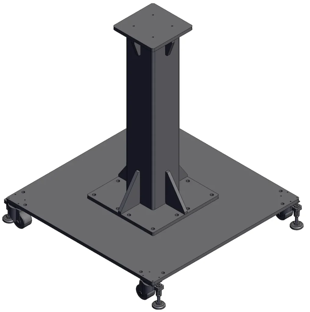
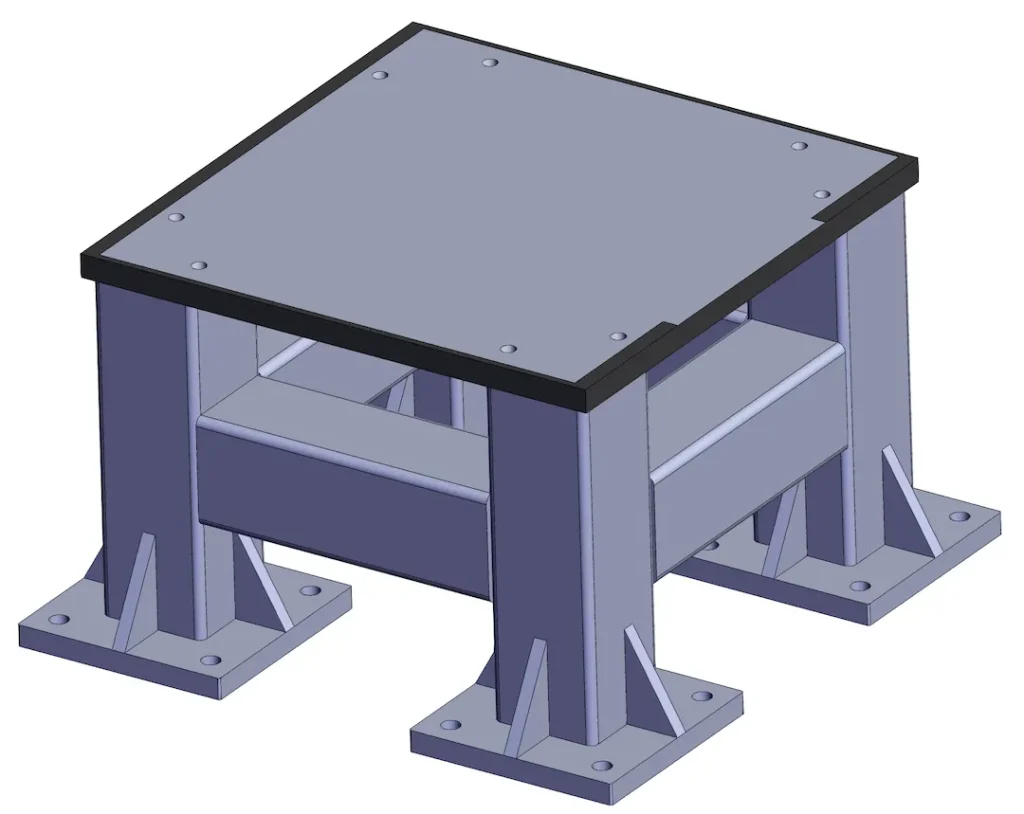
- Bases de robots: cadres à profil bas avec plaques lourdes et patins de nivellement; typique 600–1200mm empreintes carrées.
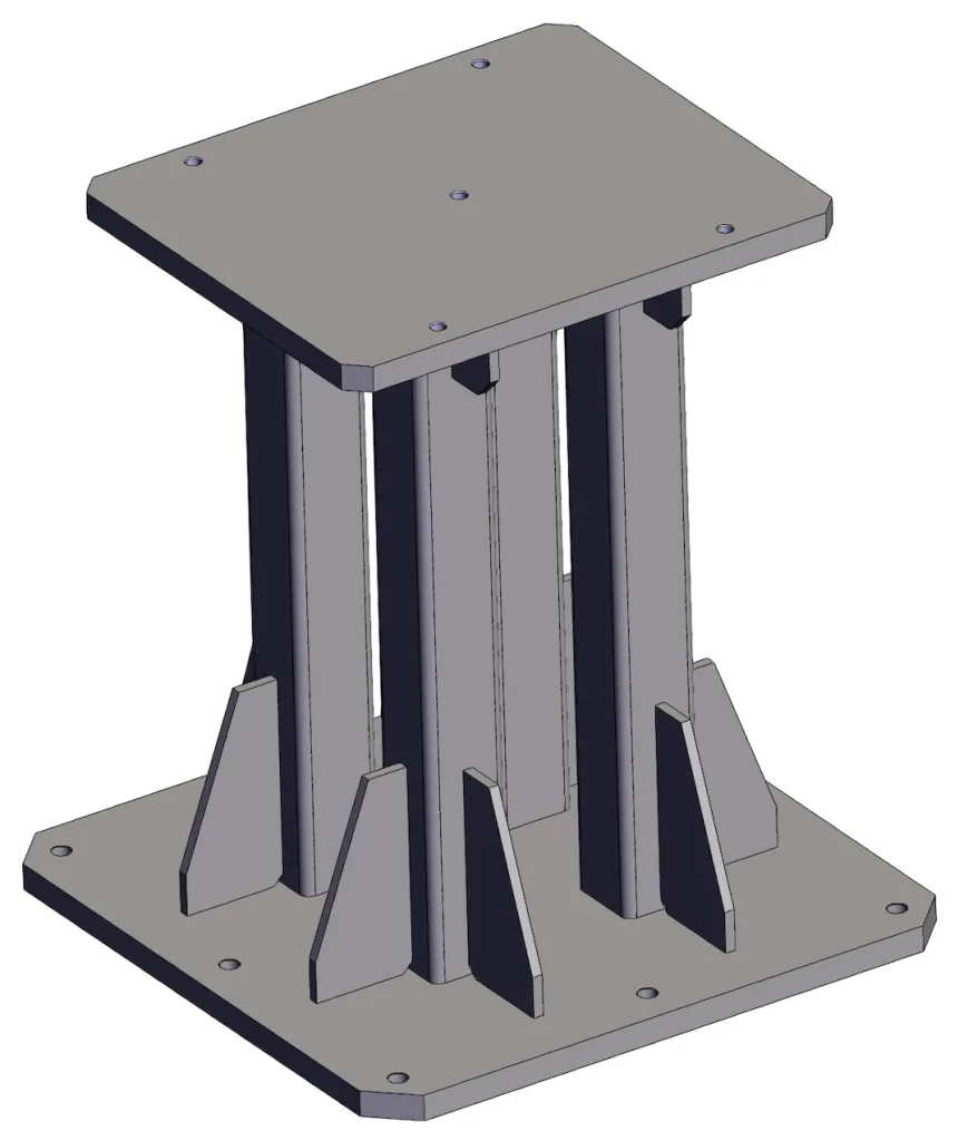
- Contremarches/piédestaux: hauteur 200–1000mm avec raidisseurs internes; coussinet supérieur usiné et percé selon le modèle de robot.
- Cadres de cellules: embases modulaires pour cellules multi-robots, avec interfaces de surveillance et de service.
- Patins utilitaires: Structures RHS/plaques supportant les vannes, pouvoir, et refroidissement sur châssis mobile ou fixe. Le dimensionnement dépend de l'empreinte du robot, charges dynamiques, et stratégie d'ancrage (PCD, plages d'emplacements, poches de coulis). Indiquez votre cible vibrations/rigidité ou inclinaison/inclinaison autorisée : notre assistance technique dimensionnera les sections en conséquence.
Qualité & Essai
Ce que nous vérifions (Vermont, Dft, Contrôles CMM; PT / MT / RT en option) et documentation (WPS / PQR, Coc)
- Inspection visuelle (Vermont 100%) de toutes les soudures; ISO 2808 Dft contrôles de l'épaisseur du revêtement.
- Cmm vérification de PCD, tampons de référence, et coplanarité/parallélisme des pads; documenté niveau chèques.
- NDT en option: PT/MT/RT pour les joints critiques selon votre plan.
- Documents livrés: WPS / PQR (le cas échéant), Coc, certificats de matériaux, et rapports d'inspection.
Prix & Délai de mise en œuvre
MOQ, exemples/versions pilotes, Conducteurs de coûts indicatifs (Pas de prix difficiles)
- MOQ: flexible pour les prototypes/pilotes; les séries économiques commencent à quelques dizaines selon la taille.
- Délai de mise en œuvre: des prototypes généralement 2–4 semaines après avoir signé la signature; production 4–7 semaines en fonction de la file d'attente de revêtement et du contenu de l'usinage.
- Facteurs de coûts: épaisseur et qualité de la plaque, usinage de plages/alésages de référence, système de revêtement (poudre vs e-coat), classe de tolérance (ISO 13920 B contre C), Portée des CND, et kit emballage/export. Fournir des dessins avec planéité/parallélisme cible et modèle de robot/PCD pour affiner le devis.
Normes & Conformité
Normes / certifications pertinentes & documentation fournie
Nous construisons pour ISO 13920, ISO 2768, et ISO 2553 symbolisant, avec acceptation de soudure à ISO 5817 (classe B / C). Les revêtements sont sélectionnés et vérifiés pour ISO 12944 avec préparation à ISO 8501. Sur demande, les projets peuvent faire référence AWS D1.1 pour des conseils structurels et intégrer les qualifications WPS/PQR et de soudeur en conséquence.
FAQ
Q1. Quels matériaux recommandez-vous?
Aciers au carbone Q235 / S235 ou Q355 / S355 offrir le meilleur rapport rigidité/prix. Choisir 304/316 inoxydable pour l'hygiène/exposition à la corrosion, ou 6061/6082 aluminium pour élévateurs sensibles au poids.
Q2. Quelles cibles de rigidité/de planéité sont typiques ??
Les conseils courants sont planéité du tampon ≤0,5–1,0 mm et parallélisme ≤0,5–1,0 mm sur les supports de montage, avec globalement équerrage ≤1,0–1,5 mm/m. Nous dimensionnerons les sections pour respecter vos limites de déflexion.
Q3. Dans quelle mesure pouvez-vous maintenir les tolérances PCD et de référence?
Les trous découpés au laser et les tampons de référence usinés CNC permettent régulièrement d'obtenir ±0,1–0,2 mm emplacement sur les PCD en fonction de la taille; nous vérifions avec Cmm et fournir des rapports.
Q4. Quelle classe de soudure utilisez-vous?
joints sensibles/critiques à ISO 5817 classe B, joints généraux du cadre à Classe C, sauf si vos spécifications exigent le contraire.
Q5. Quels revêtements et fonds masqués pouvez-vous fournir?
Manteau en poudre (tapez. 70–100 μm), placage de zinc, coat électronique, ou peindre. Nous masquons mise à la terre/ESD points par dessin et peut ajouter des étiquettes pour le collage.
Q6. Quels sont le MOQ et le délai de livraison?
Prototypes bienvenus; la série MOQ dépend de la taille et du revêtement. Délais de livraison typiques: 2–4 semaines (prototype), 4–7 semaines (série).
Q7. De quels dessins avez-vous besoin pour citer?
Fournir L×L×H, robot empreinte et PCD, tolérances cibles (planéité/parallélisme), système de revêtement, et documents CND/AQ requis.
Télécharger le dessin / Obtenez un devis
Prêt à dimensionner votre base ou contremarche? Téléchargez votre dessin (ÉTAPE/DWG/PDF) avec modèle de robot, PCD, et objectifs de tolérance. Notre équipe d'ingénierie vous proposera une solution rentable, conception testable et émettre un message rapide service personnalisé citation.