概要 & 使用例

エイブルハードウェアはカスタムロボットベースを設計および製造します, ライザー, 台座, 安定性を実現する溶接セルフレーム, 産業用ロボット用の精密プラットフォーム, 協働ロボット, および自動化周辺機器. 輸出対応の QA を備えたメトリック仕様に基づいて構築, 当社のアセンブリは、剛性の高い溶接構造と精密機械加工されたデータム パッドおよびアンカー パターンを組み合わせて、シフトに次ぐシフトでプログラムが期待する位置にロボットを正確に保持します。.
目次
ロボット工学にこのソリューションが必要な理由 & 自動化環境
ロボットの精度はその下にある構造によって決まる. 当社の溶接ベースおよびライザー ソリューションにより剛性が向上します。, リーチを高める, 振動と熱の影響を制御しながら視線を改善します。. レベリングパッド (M20~M30) 精密シムにより迅速な取り付けが可能; ケーブルトレイとパススルーにより配線が簡素化されます; データムパッドにより CMM 検証が可能; および保護/フェンシング インターフェイスによりセルの統合が高速化されます. 関連する機能については、次のサイトを参照してください。 カスタムメタルフレーム, 自動溶接, そして パウダーコーティング.
ロボットセルの代表的な用途 (基地, ライザー, セルフレーム)
- ハンドリングの高さ/リーチを設定するロボットのベースとライザー, 溶接, パレタイジング, または検査
- 統合されたケーブル管理を備えたセルフレーム, ユーティリティレール, インターフェイスの保護
- グラウトポケット付き台座, スロット付きアンカープレート, およびマスクされたボンディングポイント (ESD/アース)
- コントローラー用ユーティリティスキッド, 空気圧, ロボットの下または横の配電と
技術的特性
材料, プロフィール & 負荷; 公差 (ISO13920/ISO 2768) & 溶接品質 (ISO 5817)
- 材料 & 成績: Q235/S235 および Q355/S355 はコスト効率の高い剛性を実現; オプション 304/316 衛生/腐食に優れたステンレス製; オプション 6061/6082 重量に敏感なライザー用のアルミニウム.
- プロフィール & 厚さ: RHS/SHS, 皿, チャネル; 一般的なチューブサイズ 40×40×2~120×60×4mm; ベース/トッププレート 10–30mm; ガセット 6–10mm.
- 寸法 & 負荷: 典型的な 長さ×幅×高さ 600×600×200~2000×1500×1000mm ロボットとアーム先端ツールに合わせたサイズのペイロードを搭載. ロボット機種に合わせます 足跡 (んん) そして アンカーパターン (PCD/スロット) OEM仕様に準拠.
- 公差 & ジオメトリ制御: ISO 13920 クラス 紀元前 溶接構造用; ISO 2768 男女別 一般的な. ガイダンス: パッドの平坦度 ≤0.5 ~ 1.0 mm, パッドの平行度 ≤0.5 ~ 1.0 mm, 直角度 ≤1.0 ~ 1.5 mm/m. 溶接記号ごと ISO 2553.
- 溶接品質: ISO 5817 クラスB 可視/重要なジョイント上; クラスC 他の場所で. 構造リファレンス AWS D1.1 リクエストに応じて利用可能.
仕上げ & 腐食防止 (ISO12944/ISO 8501)
- 表面処理: に ISO 8501.
- コーティング: パウダーコート (典型的な RAL, 70–100μm), 亜鉛メッキ, 電子コート, または環境ごとに選択された工業用塗料を使用して ISO 12944 カテゴリ.
- 電気/ESD: マスクされたグランドとボンディングポイントが指定されている場合に提供される.
- ラベル & 安全性: 資産ラベル, リフト/センターマーク, ご要望に応じてトルク/アンカーに関するメモも提供します.
製造オプション
自動/ロボット MIG (指定されている場合は TIG), 治具 & 備品, 再現性
私たちが使用するのは 自動/ロボット MIG 炭素鋼フレームと ティグ ステンレス/化粧継ぎ目が指定されている場合. ひたむきな 治具 & 備品 パイロットビルドとシリーズ実行全体で再現性のある直角度と穴の PCD 位置を確保します。. 必要に応じてWPS/PQRが利用可能.
二次作戦: レーザー切断, 曲げ, 機械加工; ケーブル管理, コーティング & パッケージング
- レーザー切断 ベース/トッププレートの, PCD, スロット付きアンカー; 曲げ・成形 ガセットとトレイ機能用.
- CNC加工 データムパッドの, 穴, 測定された共平面性の界面と界面.
- 統合の詳細: ケーブルトレイ, パススルーグロメット, コントローラシェルフ, 目を持ち上げる.
- コーティング 自社回線・提携回線経由; パッケージング 保護ラップ付き, ボルトキット, シム, 組み立てメモ, 輸出用の木箱/パレット化された貨物.
種類 & ジオメトリ
ロボット工学用の一般的なアセンブリ (ロボットベース, ライザー, 台座, セルフレーム, ユーティリティスキッド) & サイズバンド
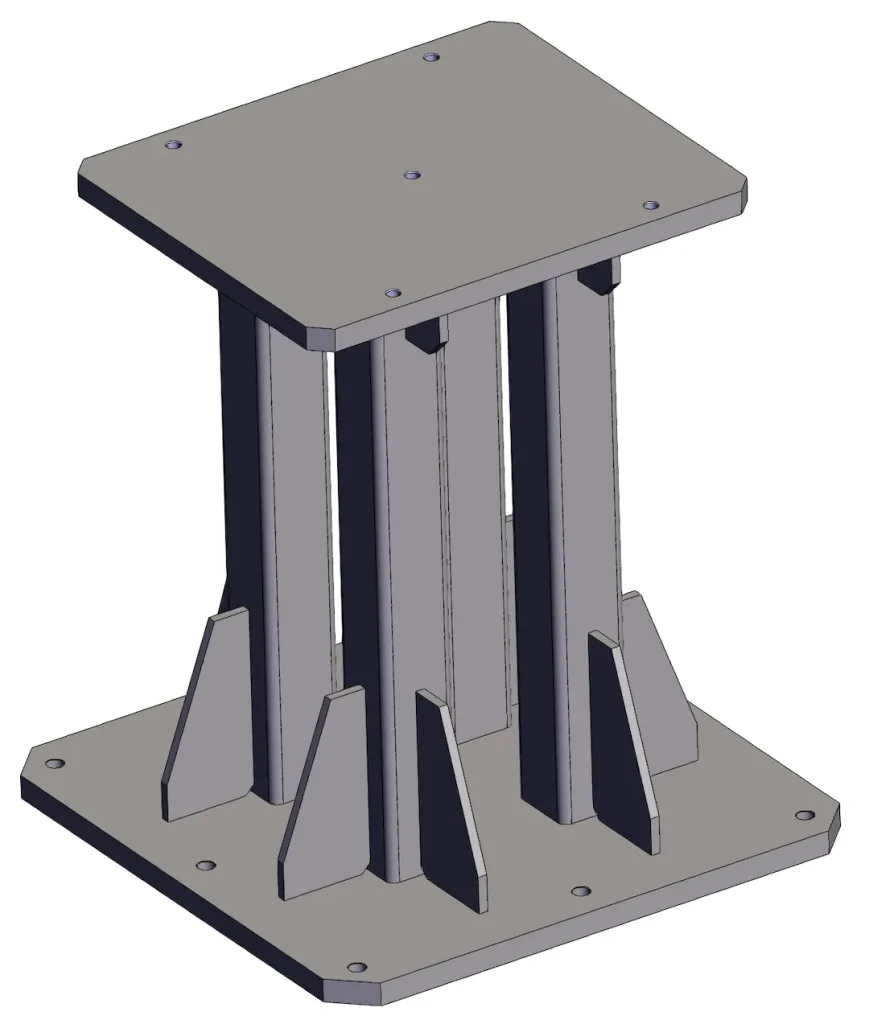
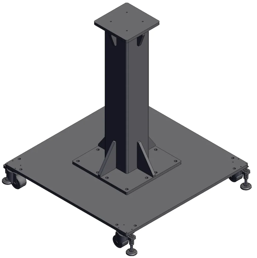
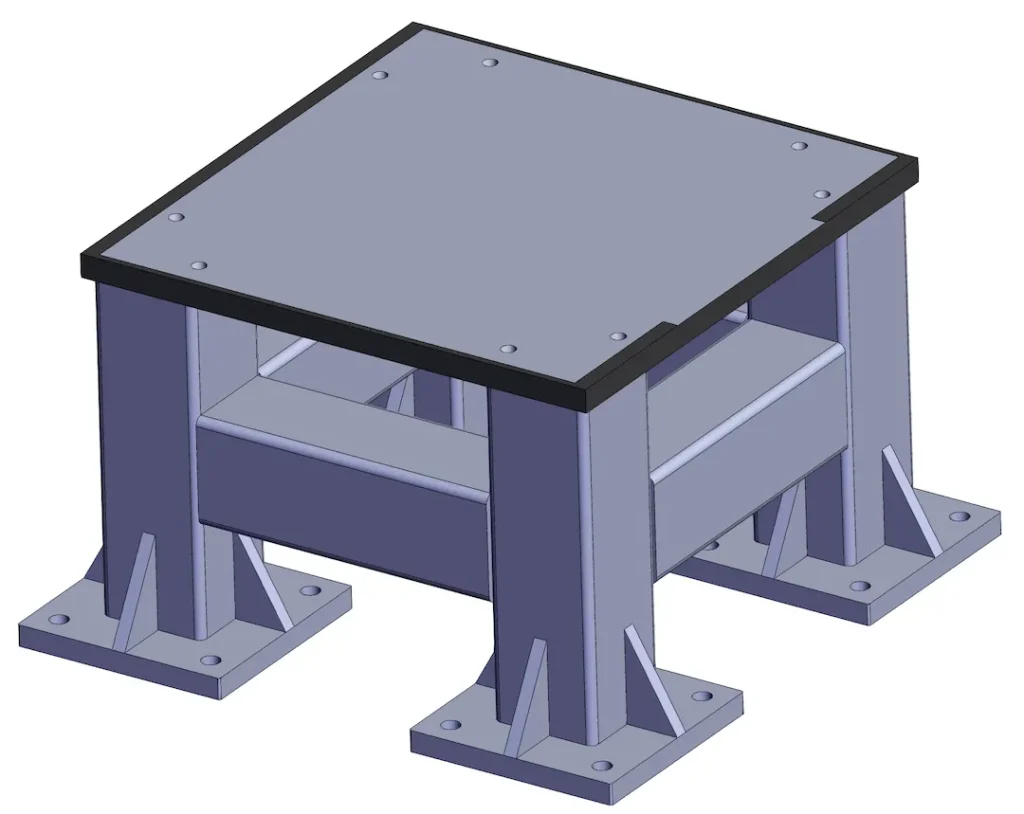
- ロボットベース: 厚手のプレートとレベリングパッドを備えた薄型フレーム; 典型的な 600–1200mm 平方フットプリント.
- ライザー/ペデスタル: 身長 200–1000mm 内部補強材付き; 上部パッドはロボットモデルごとに機械加工および穴あけ済み.
- セルフレーム: マルチロボットセル用のモジュラーサブベース, 保護およびサービスインターフェイスを備えた.
- ユーティリティスキッド: バルブをサポートするRHS/プレート構造, 力, 可動フレームまたは固定フレームでの冷却. サイジングはロボットの設置面積によって決まります, 動的荷重, そしてアンカリング戦略 (PCD, スロット範囲, グラウトポケット). ターゲットを指定してください 振動・剛性 または許容される傾き/傾き - 当社のエンジニアリング サポートがそれに応じてセクションのサイズを決定します.
品質 & テスト
私たちが検証すること (VT, DFT, 三次元測定機チェック; オプションの PT/MT/RT) とドキュメント (WPS/PQR, CoC)
- 目視検査 (VT 100%) すべての溶接の; ISO 2808 DFT コーティングの厚さのチェック.
- 三次元測定機 の検証 PCD, データムパッド, パッドの同一平面性/平行度; 文書化された 水平性 小切手.
- オプションのNDT: プランに応じた重要なジョイントの PT/MT/RT.
- 納品されたドキュメント: WPS/PQR (該当する場合), CoC, 材料証明書, および検査報告書.
価格設定 & リードタイム
Moq, サンプル/パイロット ビルド, 示唆的なコスト要因 (厳しい価格はありません)
- Moq: プロトタイプ/パイロットに柔軟に対応; economical series start at low dozens depending on size.
- Lead time: prototypes typically 2–4 weeks after drawing sign-off; 生産 4–7 weeks depending on coating queue and machining content.
- Cost drivers: plate thickness and grade, machining of datum pads/bores, coating system (powder vs e-coat), tolerance class (ISO 13920 B vs C), NDT scope, and packaging/export kit. Provide drawings with target flatness/parallelism and robot model/PCD to refine the quote.
規格 & コンプライアンス
関連する規格/認証 & 提供されたドキュメント
We build to ISO 13920, ISO 2768, そして ISO 2553 symboling, with weld acceptance to ISO 5817 (class B/C). Coatings are selected and verified to ISO 12944 with prep to ISO 8501. On request, projects can reference AWS D1.1 for structural guidance and incorporate WPS/PQR and welder qualifications accordingly.
よくある質問
Q1. どの教材がおすすめですか?
Carbon steels Q235/S235 または Q355/S355 offer the best stiffness-to-price. Choose 304/316 stainless for hygiene/corrosion exposure, または 6061/6082 重量に敏感なライザー用のアルミニウム.
第2四半期. 典型的な剛性/水平度の目標?
Common guidance is パッドの平坦度 ≤0.5 ~ 1.0 mm そして 平行度≦0.5~1.0mm 取り付けパッド全体にわたって, 全体的に 直角度 ≤1.0 ~ 1.5 mm/m. たわみ制限を満たすようにセクションのサイズを決定します.
Q3. PCD とデータムの公差をどの程度厳密に保持できるか?
レーザーカットの穴と CNC 加工のデータム パッドにより、日常的に次のような成果が得られます。 ±0.1~0.2mm サイズに応じたPCD上の位置; で検証します 三次元測定機 そしてレポートを提供する.
Q4. どの溶接クラスを使用しますか?
可能/重要なジョイントへ ISO 5817 クラスB, 一般的なフレームジョイントに クラスC, 仕様で別途必要がない限り.
Q5. どのようなコーティングとマスキングされた下地を提供できますか?
パウダーコート (タイプ. 70–100μm), 亜鉛メッキ, 電子コート, またはペイント. マスクをします 接地/ESD 図面ごとにポイントがあり、結合用のラベルを追加できます.
Q6. MOQとリードタイムはどれくらいですか?
プロトタイプ大歓迎; シリーズのMOQはサイズとコーティングによって異なります. 一般的なリードタイム: 2–4 weeks (プロトタイプ), 4–7 weeks (シリーズ).
Q7. 見積に必要な図面は何ですか?
提供する 長さ×幅×高さ, ロボット 設置面積とPCD, 目標許容差 (平面度・平行度), coating system, および NDT/QA 文書が必要です.
図面をアップロードする / 見積もりを取得する
ベースまたはライザーのサイズを調整する準備ができています? 図面をアップロードする (STEP/DWG/PDF) ロボットモデル付き, PCD, および許容範囲の目標. 弊社エンジニアリングチームがコスト効率の高いご提案をさせていただきます, テスト可能な設計と迅速な発行 カスタムサービス 引用.