Überblick & Anwendungsfälle

Able Hardware entwirft und fertigt maßgeschneiderte Roboterbasen, Riser, Sockel, und geschweißte Zellrahmen, die für Stabilität sorgen, Präzise Plattformen für Industrieroboter, Cobots, und Automatisierungsperipherie. Gebaut nach metrischen Spezifikationen mit exportfähiger Qualitätssicherung, Unsere Baugruppen kombinieren steife Schweißstrukturen mit präzisionsgefertigten Bezugspunkten und Verankerungsmustern, um Ihren Roboter genau dort zu halten, wo Ihr Programm ihn erwartet – Schicht für Schicht.
Inhaltsverzeichnis
Warum diese Lösung für die Robotik? & Automatisierungsumgebungen
Die Genauigkeit eines Roboters ist nur so gut wie die Struktur darunter. Unsere geschweißten Basis- und Riser-Lösungen erhöhen die Steifigkeit, Reichweite erhöhen, und die Sichtlinie verbessern und gleichzeitig Vibrationen und thermische Effekte kontrollieren. Nivellierpads (M20–M30) und Präzisionsunterlegscheiben ermöglichen eine schnelle Installation; Kabelrinnen und Kabeldurchführungen vereinfachen die Verlegung; Bezugspads ermöglichen die KMG-Überprüfung; und Schutz-/Zaunschnittstellen beschleunigen die Zellintegration. Siehe verwandte Funktionen unter Benutzerdefinierte Metallrahmen, automatisches Schweißen, und Pulverbeschichtung.
Typische Anwendungen in Roboterzellen (Basen, Riser, Zellrahmen)
- Robotersockel und -erhöhungen zum Einstellen der Höhe/Reichweite für die Handhabung, Schweißen, Palettieren, oder Inspektion
- Zellenrahmen mit integriertem Kabelmanagement, Versorgungsschienen, und Schutzschnittstellen
- Sockel mit Fugentaschen, geschlitzte Ankerplatten, und maskierte Klebepunkte (ESD/Erde)
- Utility-Skids für Controller, Pneumatik, und Stromverteilung unter oder neben dem Roboter
Technische Eigenschaften
Materialien, Profile & Lasten; Toleranzen (ISO 13920/ISO 2768) & Schweißqualität (ISO 5817)
- Materialien & Noten: Q235/S235 und Q355/S355 für kostengünstige Steifigkeit; optional 304/316 rostfrei für Hygiene/Korrosion; optional 6061/6082 Aluminium für gewichtsempfindliche Tragegurte.
- Profile & Dicke: RHS/SHS, Teller, Kanal; typische Rohrgrößen 40× 40 × 2 bis 120 × 60 × 4 mm; Grund-/Oberplatten 10–30 mm; Zwickel 6–10 mm.
- Maße & Lasten: Typisch L×B×H 600×600×200 bis 2000×1500×1000 mm mit Nutzlasten, die auf Ihren Roboter und Ihre End-of-Arm-Werkzeuge abgestimmt sind. Wir passen das Robotermodell an Fußabdrücke (mm) und Ankermuster (PCD/Steckplätze) gemäß OEM-Spezifikationen.
- Toleranzen & Geometriekontrolle: ISO 13920 Klasse B/c für Schweißkonstruktionen; ISO 2768 m/f allgemein. Anleitung: Pad-Ebenheit ≤0,5–1,0 mm, Parallelität der Pads ≤0,5–1,0 mm, Rechtwinkligkeit ≤1,0–1,5 mm/m. Schweißsymbole pro ISO 2553.
- Schweißqualität: ISO 5817 Klasse b an sichtbaren/kritischen Fugen; Klasse c anderswo. Struktureller Bezug AWS D1.1 auf Anfrage erhältlich.
Oberflächen & Korrosionsschutz (ISO 12944/ISO 8501)
- Oberflächenvorbereitung: zu ISO 8501.
- Beschichtungen: Pulvermantel (typisch Ral, 70–100 μm), Zinkbeschichtung, E-Coat, oder Industriefarbe, die je nach Umgebung ausgewählt wird ISO 12944 Kategorien.
- Elektrik/ESD: Maskierte Erdungen und Verbindungspunkte werden bereitgestellt, sofern angegeben.
- Etiketten & Sicherheit: Asset-Labels, Hebe-/Mittelmarkierungen, und Drehmoment-/Ankerhinweise auf Anfrage.
Fertigungsoptionen
Automatische/Robotermig (und TIG, wenn angegeben), Vorrichtungen & Vorrichtungen, Wiederholbarkeit
Wir verwenden Automatische/Robotermig für Kohlenstoffstahlrahmen und WIG wo rostfreie/kosmetische Nähte vorgeschrieben sind. Gewidmet Vorrichtungen & Vorrichtungen Gewährleisten Sie eine wiederholbare Rechtwinkligkeit und Loch-PKD-Position bei Pilot- und Serienläufen. WPS/PQR sind bei Bedarf verfügbar.
Sekundäre Ops: Laserschnitt, biegen, Bearbeitung; Kabelmanagement, Beschichtung & Verpackung
- Laser schneiden der Grund-/Oberplatten, PCDs, und Schlitzanker; Biegung/Bildung für Zwickel und Tablettmerkmale.
- CNC-Bearbeitung von Bezugspads, Bohrungen, und Grenzflächen für gemessene Koplanarität.
- Integrationsdetails: Kabelschalen, Durchgangstüllen, Controller-Regale, Augen heben.
- Beschichtung über Inhouse-/Partnerleitungen; Verpackung mit Schutzhülle, Schraubensätze, Unterlegscheiben, Montagehinweise, und Lieferungen in Kisten/Paletten für den Export.
Typen & Geometrie
Gängige Baugruppen für die Robotik (Roboterbasen, Riser, Sockel, Zellrahmen, Versorgungskufen) & Größenbänder
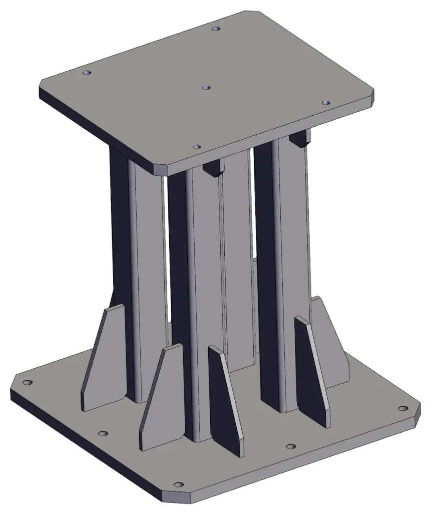
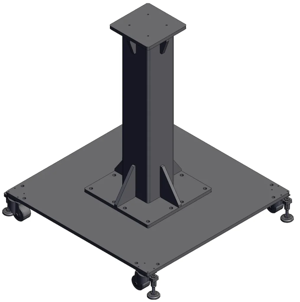
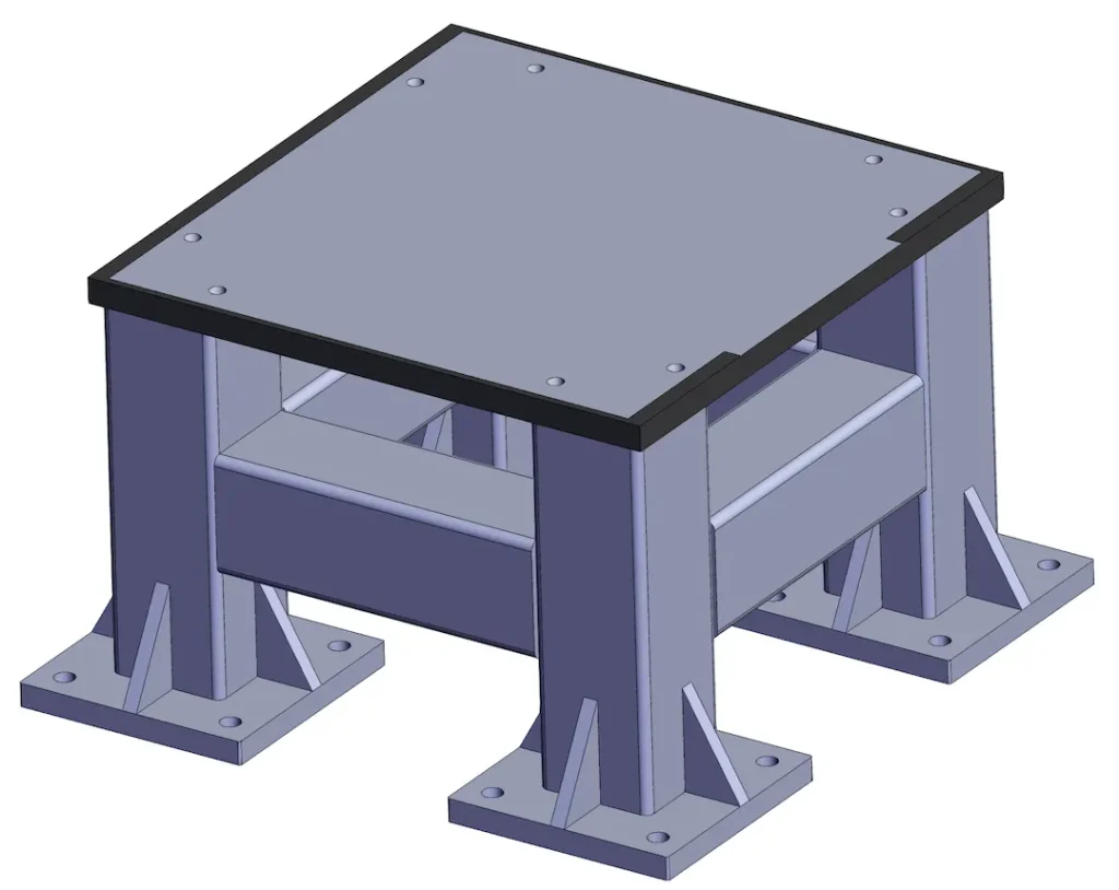
- Roboterbasen: Niedrigprofilrahmen mit schweren Platten und Nivellierplatten; typisch 600–1200 mm quadratische Grundfläche.
- Setzstufen/Sockel: Höhe 200–1000 mm mit innenliegenden Versteifungen; Oberes Polster je nach Robotermodell bearbeitet und gebohrt.
- Zellrahmen: modulare Grundplatten für Multiroboterzellen, mit Schutz- und Serviceschnittstellen.
- Versorgungskufen: RHS/Plattenstrukturen zur Unterstützung von Ventilen, Leistung, und Kühlung auf einem mobilen oder festen Rahmen. Die Größenbestimmung wird durch den Fußabdruck des Roboters bestimmt, dynamische Belastungen, und Verankerungsstrategie (PCD, Slot-Bereiche, Fugentaschen). Geben Sie Ihr Ziel an Vibration/Steifigkeit oder zulässige Neigung/Neigung – unser technischer Support wird die Abschnitte entsprechend dimensionieren.
Qualität & Testen
Was wir überprüfen (Vt, DFT, CMM-Prüfungen; Optionales PT/MT/RT) und Dokumentation (WPS/PQR, Kok)
- Visuelle Inspektion (Vt 100%) aller Schweißnähte; ISO 2808 DFT Kontrolle der Schichtdicke.
- CMM Überprüfung von PCDs, Bezugspads, und Pad-Koplanarität/Parallelität; dokumentiert Ebenheit Schecks.
- Optional ndt: PT/MT/RT für kritische Verbindungen gemäß Ihrem Plan.
- Dokumente geliefert: WPS/PQR (wenn anwendbar), Kok, Materialzertifikate, und Inspektionsberichte.
Preisgestaltung & Vorlaufzeit
MOQ, Beispiel-/Pilotbauten, Indikative Kostenfahrer (Keine harten Preise)
- MOQ: flexibel für Prototypen/Piloten; wirtschaftliche Serien beginnen je nach Größe bei niedrigen Dutzenden.
- Vorlaufzeit: Prototypen typischerweise 2–4 Wochen nach Zeichnungsfreigabe; Produktion 4–7 Wochen Abhängig von der Beschichtungswarteschlange und dem Bearbeitungsinhalt.
- Kosten Treiber: Blechdicke und Güte, Bearbeitung von Bezugsflächen/Bohrungen, Beschichtungssystem (Pulver vs. E-Beschichtung), Toleranzklasse (ISO 13920 B vs c), ZfP-Bereich, und Verpackungs-/Export-Kit. Stellen Sie Zeichnungen mit Soll-Ebenheit/Parallelität und Robotermodell/PKD bereit, um das Angebot zu verfeinern.
Standards & Einhaltung
Relevante Standards/Zertifizierungen & Dokumentation bereitgestellt
Wir bauen darauf ISO 13920, ISO 2768, und ISO 2553 symbolisierend, mit Schweißabnahme bis ISO 5817 (Klasse B/c). Beschichtungen werden ausgewählt und geprüft ISO 12944 mit Vorbereitung auf ISO 8501. Auf Anfrage, Projekte können darauf verweisen AWS D1.1 zur strukturellen Orientierung und entsprechende WPS/PQR- und Schweißerqualifikationen einbeziehen.
FAQ
Q1. Welche Materialien empfehlen Sie??
Kohlenstoffstähle Q235/S235 oder Q355/S355 bieten das beste Steifigkeits-Preis-Verhältnis. Wählen 304/316 rostfrei für Hygiene/Korrosionsschutz, oder 6061/6082 Aluminium für gewichtsempfindliche Tragegurte.
Q2. Welche Steifigkeits-/Ebenheitsziele sind typisch??
Allgemeine Anleitung ist Pad-Ebenheit ≤0,5–1,0 mm und Parallelität ≤0,5–1,0 mm über Montagepads, mit insgesamt Rechtwinkligkeit ≤1,0–1,5 mm/m. Wir passen die Abschnitte so an, dass sie Ihren Durchbiegungsgrenzen entsprechen.
Q3. Wie eng können Sie die PKD- und Bezugstoleranzen einhalten??
Lasergeschnittene Löcher und CNC-gefräste Bezugspunkte erreichen dies routinemäßig ±0,1–0,2 mm Position auf PCDs je nach Größe; Wir verifizieren mit CMM und Berichte erstellen.
Q4. Welche Schweißnahtklasse verwenden Sie??
isible/kritische Verbindungen zu ISO 5817 Klasse b, allgemeine Rahmenverbindungen zu Klasse c, es sei denn, Ihre Spezifikation erfordert etwas anderes.
Q5. Welche Beschichtungen und Abdeckgründe können Sie anbieten??
Pulvermantel (typ. 70–100 μm), Zinkbeschichtung, E-Coat, oder malen. Wir maskieren Erdung/ESD Punkte pro Zeichnung und können Beschriftungen für die Verbindung hinzufügen.
Q6. Wie hoch sind die Mindestbestellmenge und die Vorlaufzeit??
Prototypen willkommen; Die Mindestbestellmenge der Serie hängt von der Größe und der Beschichtung ab. Typische Lieferzeiten: 2–4 Wochen (Prototyp), 4–7 Wochen (Serie).
Q7. Welche Zeichnungen benötigen Sie für ein Angebot??
Bieten L×B×H, Roboter Footprint und PCD, Zieltoleranzen (Ebenheit/Parallelität), Beschichtungssystem, und NDT/QA-Dokumente erforderlich.
Zeichnung hochladen / Holen Sie sich ein Angebot
Bereit zum Anpassen Ihrer Basis oder Ihres Risers? Laden Sie Ihre Zeichnung hoch (STEP/DWG/PDF) mit Robotermodell, PCD, und Toleranzziele. Unser Engineering-Team wird Ihnen einen kostengünstigen Vorschlag unterbreiten, Testbares Design und schnelle Ausgabe Maßgeschneiderter Service Zitat.