)
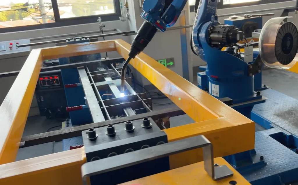
Table of Contents
Welded frames carry machines, conveyors, carts, and fixtures. Getting the right tolerance scheme is the difference between smooth installation and costly rework. As a China-based OEM/ODM factory, Able Hardware builds precision frames using automatic/robotic MIG (and TIG when specified), integrated CNC machining, and export-ready quality documentation. This guide shows how to apply GD&T to welded frames so you can buy once and install fast.
Where GD&T Adds Value
- Communicates function (fit, form, and orientation) instead of guessing “tight everywhere.”
- Prevents over-tolerancing that inflates weld time, fixturing, machining, and coating rework.
- Enables scalable inspection—from weld gauges to CMM/laser scanning—aligned to risk.
For production examples, see our Custom Metal Frames and Welding Trolley Carts.
Datum Strategy for Frames
Choose Stable, Functional Datums
- Primary (A): The mounting plane or base pads that interface with the floor, machine bed, or skid. Define A as a broad, stable plane after any post-weld machining.
- Secondary (B): A long reference rail or machined edge that drives part orientation along length.
- Tertiary (C): A cross-member or machined hole/slot that locks rotation.
Tip: If the frame is powder-coated, define datums on non-coated machined pads to avoid stack from coating thickness.
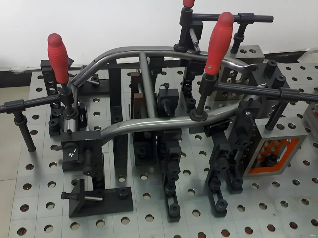
Sequence and Fixturing
Call out “Datums after weld, before coating” if pads are spot-faced post-weld. We use dedicated fixtures and robotic beads to stabilize heat input.
GD&T Controls That Work Best on Welded Frames
Straightness & Flatness
- Straightness of tube rails: 0.5–1.0 mm per metre typical for as-welded members.
- Flatness of base plane (A): 0.3–0.8 mm per 300 mm as-welded; 0.1–0.3 mm after machining.
Parallelism & Perpendicularity (Squareness)
- Parallelism between upper deck and base A: 0.3–0.6 mm per 300 mm as-welded; 0.1–0.2 mm machined.
- Perpendicularity of uprights to A: 0.2–0.5 mm per 100 mm.
Position for Hole Groups
Use true position with MMC for bolt patterns on pads and brackets:
- Ø0.3–0.6 mm (machined) or Ø0.8–1.5 mm (as-welded pierced plates) to datums A|B|C.
- For long rails, apply composite position to hold pattern-to-pattern repeatability while allowing rail growth.
Profile for Envelopes
- Profile of a surface 0.8–1.5 mm controls overall tube frame envelope without over-constraining every member.
Runout (When Needed)
- Use circular/total runout on shafts/bosses welded to frames (rare). Otherwise, position + perpendicularity is cleaner.
Weld Quality Level & Symbols
- Specify symbols per ISO (or AWS if your standard). Reference ISO 5817 quality levels:
- Level C (moderate) for non-critical cart frames.
- Level B (stringent) for machine bases or precision mounting pads.
- Define throat size, length, pitch for intermittent welds to manage heat input.
- State acceptance standard and inspection method (visual, fillet gauges, dye-pen, measurement plan).
Realistic Tolerances by Process Route
As-Welded (Fixture-Controlled)
- Flatness of base A: 0.5–1.0 mm per 300 mm.
- Perpendicularity of uprights: 0.3–0.6 mm/100 mm.
- Position on pierced holes: Ø0.8–1.5 mm.
Weld + Post-Machining
- Spot-faced pads and reamed holes: flatness 0.1–0.2 mm; position Ø0.2–0.4 mm.
- We often weld oversize pads, stress-relieve if needed, then CNC to tolerance.
Distortion Control Plan
Materials & Thickness
- Carbon steel (S235–S355) is most predictable for robotic MIG.
- Stainless (304/316) needs tighter heat control and sometimes larger profiles to resist pull.
- Balance wall thickness across opposing members; asymmetry increases bow.
Process & Heat Input
- Staggered, symmetric bead sequence with robot paths; interpass spacing to cool; copper backing for critical edges.
- Intermittent welds where feasible to reduce mass and heat.
Stress Relief & Machining
- For heavy frames or tight pads: low-temp stress relief, then face mill/ream.
- Define machining allowance (e.g., +1.0–1.5 mm on pads).
Coating & Masking
- Powder coat adds 60–100 µm thickness; mask datum faces and threaded holes.
- Note any Rz targets after coating for sealing surfaces. See powder coating.
What to Put on the Drawing/RFQ
- 3D model (STEP/IGES) + fully dimensioned 2D with datums A|B|C.
- GD&T feature control frames for base flatness, squareness, hole positions, and key profiles.
- Weld callouts with ISO 5817 level, throat, length, pitch, process (MIG/TIG), and sequence notes if critical.
- Critical-to-Quality (CTQ) list highlighting features we must measure 100%.
- Material grade, tube size, wall thickness, and any pre-galv or pickling requirements.
- Coating spec (powder, shot-blast class, color/texture) and masked areas.
- Inspection level (FAI, PPAP-like, or batch) and required records.
For engineering templates and checklists, visit engineering.
Inspection Plan & Reporting
We align inspection with risk and your audit needs:
- First Article with full layout to datums (portable CMM or laser scan for large frames).
- Go/No-Go gauges for squareness and envelope checks on the floor.
- Weld gauges + visual per ISO 5817; optional NDT on critical joints.
- Pack with shock/tilt indicators and corrosion protection; export-grade crating.
Cost & Lead-Time Drivers (No Absolute Prices)
- Tolerance class: tighter flatness/position and Level B welds increase fixturing, bead time, and machining.
- Member count & weld length: more joints = more heat = more rework risk.
- Material & size: stainless and thick-wall sections raise cycle time and consumables.
- Post-machining & stress relief: adds operations but enables tighter GD&T.
- Finish: powder texture, masking, and color changes influence takt.
- Volume & repeatability: repeat orders justify dedicated jigs for lower unit cost.
- Documentation depth: FAI/PPAP-style packets add metrology time.
Why Able Hardware
- Automatic/robotic MIG lines with consistent heat input; TIG available for thin or visible joints.
- In-house laser cutting & CNC machining for post-weld pads and precision holes.
- ISO-aligned QC with export-ready documents and packaging.
- Proven supply for carts, racks, and machine bases worldwide.
FAQ
What materials do you support for welded frames?
Carbon steel (S235–S355) and stainless 304/316 as standard; aluminium by case. See custom metal frames products
Which processes do you use?
Robotic MIG for most frames; TIG for thin-gauge or cosmetic joints; post-weld CNC where GD&T requires it.
What tolerances are typical?
As-welded: flatness 0.5–1.0 mm/300 mm; perpendicularity 0.3–0.6 mm/100 mm; position Ø0.8–1.5 mm. Machined pads/holes: flatness 0.1–0.2 mm; position Ø0.2–0.4 mm.
What weld class do you build to?
ISO 5817 Level C (general) and Level B (precision). We follow your symbols and provide weld inspection records (/standards/iso-5817/).
How do coatings affect tolerances?
Powder adds 60–100 µm; we mask datums and threads, and we can spot-face after coating if needed (/services/powder-coating/).
MOQ and lead time?
MOQ from 1 prototype; serial batches priced more efficiently. Typical lead time 2–6 weeks based on size, machining, and finish.
What drawing files should I send?
STEP + 2D PDF with datums, GD&T, weld symbols, coating, and inspection notes. We’ll confirm CTQs before production.
Upload your drawing and get a quote now
Send your STEP/PDF with target GD&T, weld class, and finish notes. We’ll return a manufacturability review and a firm lead time.